一个学习汇编的小游戏:BOX-256
BOX-256
前言
最近在学习 RISC-V,但是指令太多,并且学习起来确实很无聊,所以找到了这个小游戏来学习一下汇编的思路。虽然不是真正的标准 RISC-V,但是可以作为学习路上的一个参考工具,下面是 BOX-256 的一些描述:
BOX-256 is a 8-bit fantasy computer, with 256 bytes of memory, 16 color 16x16 display. It is also a programming game, where the player tries to pass the graphics tests and optimize the code to perfection. The ultimate goal is to use as few CPU cycles or lines of code as possible, by employing multithreading and other optimization tricks.
此外,文档里提到了一些比较重要的细节这里也稍微列举一下:
Program Counter
When the execution starts, the last memory slot (FF) is used as a program counter (PC). If a second thread is started, the additional PC will be in FE, the third will be in FD and so on. Since there is no memory protection, it is possible to write into PC directly and cause execution to jump. The behaviour is identical to using JMP instruction.
这里有一个点比较容易误解的是:FF, FE,
这些地址。我们前面提到BOX-256 -- ...with 256 bytes of
memory...。所以,其实我们的 FF,FE
就是我们在内存从后往前的索引。也就是说,当我们执行一个多线程的程序时,他的
PC 分别存放在内存的倒数第一个字节,倒数第二个字节,依次类推。
Multithreading
Because of cached reads, it is generally not possible for one thread to communicate with other thread simultaneously. HOWEVER two exceptions remains: An earlier thread can write to memory address later executed by later thread. So self-modifying code is possible. An earlier thread can also write to program counter (PC) owned by a later thread to cause an immediate jump.
Vector Launched Threads
线性启动线程是基于 box-256 thread
的特性实现的,可以批量的启动线程的一个技术,这个技术是基于 box-256
的一个重要特性:当我们执行 THR A
指令时,会生成两个伪线程:
- 一个在
THR A执行完之后的下一条指令; - 一个在
THR A中的A指定的位置;
例如,对于下面这段代码:
1 | THR 010 000 000 ; 创建线程 |
在创建线程语句执行结束之后,会同时开始执行 #1 和
#2 两个语句;
利用这个特性,我们可以使用一些特殊的方式来创建线程,例如下面的例子:
1 | ; THR A 指令的作用是,在地址A启动一个线程并将被创建的线程的PC设置为A |
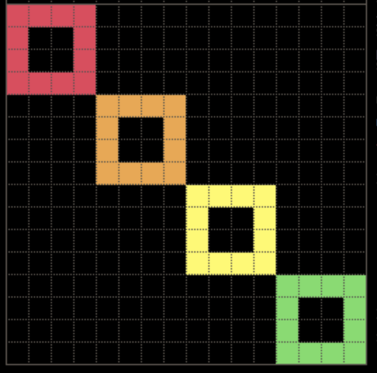
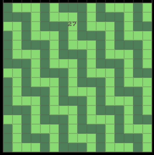
SIERPINSKI TRIANGLE
原文中关于线程的绘制给出了一个示例,使用多线程绘制
sierpinski triangle。
原文档中给出了一个使用多线程绘制 SIERPINSKI TRIANGLE
的实例,实现相当精巧,咋一看比较难以理解,但是整体思路是:使用多线程对像素点进行上色,区别在于,通过线程的合理调配来实现对于目标色块上色
008, 对于非目标色块上色
000,而这个颜色也正是我们的背景色,所以从视觉效果上来讲,我们看到的是CPU空转了一次。
而对于box256的线程来讲,他是一个非随机的伪线程,每个线程是有一个固定的执行顺序:线程的PC从
0xFF, 0xFE ... 逆序执行。
而我们这里的 MOV @10 @FB 005,就是为我们的生成的五个线程进行PC赋值的指令:
PC == 00C为我们的五个线程持续的设置PC地址,这里值得注意的是,我们线程一先执行,设置五个线程的PC分别为 24, 20, 1C, 18, 0C,但是在线程一执行完毕之后,其他四个线程执行会修改自己的PC地址,所以我们在内存里看到的实际值是 28, 24, 20, 1C, 0C;PC == 018使用颜色@29对像素点进行上色,这里有一个很容易误解的点是原始代码中是PIX 000 @28 000,看起来像素点的索引是常数,实际上我们在线程五中一直在修改这个值。理论上来说,这里这样写会更直观PIX @19 @28 000,而这里@19就指向了他自身的位置;PC == 01C这个位置,使用了一个非常巧妙的策略,我们将 \([29, 39)\) 这个区间的数据移动到 \([28, 38)\),也就是我们将所有的数据往前移动一位;而@38这个位置的值,则在线程四中进行计算;PC == 020这个线程用于生成当前色块实际对应的色块值;PC == 024修改@19,也就是我们当前绘制的像素块;
现在存在的一个最大的问题是,1C 和 20
这两行指令是如何来生成我们实际的颜色绘制结果的呢?这里必须要提到我们的点绘制算法:
一个像素点是否需要绘制,假设:
- 当前节点的位置可以表示为
memory[row][col];- \(row > 0\);
- 使用
1表示该点上色,使用0表示该点不上色;那么当且仅当
memory[row - 1][col]和memory[row - 1][col - 1]一个是1,并且另外一个为0时,该点的结果为1。
在我们的实现中,我们使用 \([28, 38]\) 这个区间来表示:
28当前节点的前面一个节点;29当前节点;- \([2A, 38]\),当前计算节点之后的
0xF个节点;
并递归的计算最终的结果。
1 | 00 - THR 004 000 000 ; |
Memory Addressing
1 | 0 = Constant value |
Examples:
1 | Address: 00 01 02 03 04 05 06 07 08 09 0A 0B ... |
Instructions
| INSTRUCTION | DESCIPTION |
|---|---|
MOVE A B
C |
Sets the value A into address B |
JMP A |
Jumps the execution into A |
PIX A B |
Outputs a pixel into index
A with color B |
JEQ A B
C |
If A equals B,
the execution jumps to C |
JNQ A B
C |
If A not equals
B, the execution jumps to C |
JGR A B
C |
If A is greater than
B, the execution jumps to C |
FLP A B
C |
Flips the values between memory address
A and memory address B. |
THR A |
Starts a new thread from memory address
A |
ADD A B
C |
Adds values A and
B together and stores the result in C |
SUB A B
C |
Subtracts B from
A and stores the result in C |
MUL A B
C |
Multiplies values A and
B and stores the results in C |
DIV A B
C |
Division A with
B and stores the result in C |
MOD A B
C |
Take modulo of A and
B and place the result in C |
Instruction Examples
1 | FLP @10 @20 004 // Flip four (4) values between memory spaces starting from @10 and @20 |
- Takes 4 values from memory that starts from address
10; - Takes 4 values from memory that starts from address
20; - Flips the values:
- Flips the values between memory address
10and memory address20; - Flips the values between memory address
11and memory address21; - ...
- Flips the values between memory address
1 | JGR 020 @30 -04 // if value in @30 is smaller or equal to 20, jump forward 4 steps (16 bytes). |
Note that you can prefix the C with minus '-' to get negative values.
Opcodes
Most of the opcodes are permutations of the same instruction. For example the ADD instruction has 8 different opcodes, depending on the 'memory depth' of the parameters.
| OPCODE | Instruction | P1 | P2 | P3 | Example |
|---|---|---|---|---|---|
| 13 | ADD | @ | 0 | @ | ADD @01 002 @03 |
| 14 | ADD | * | 0 | @ | ADD *01 002 @03 |
| 15 | ADD | @ | @ | @ | ADD @01 @02 @03 |
| 16 | ADD | * | @ | @ | ADD *01 @02 @03 |
| 17 | ADD | @ | * | @ | ADD @01 *02 @03 |
| 18 | ADD | * | 0 | * | ADD 01 002 03 |
| 19 | ADD | @ | 0 | * | ADD @01 002 *03 |
| 1A | ADD | * | @ | * | ADD 01 @02 03 |
| 1B | ADD | @ | @ | * | ADD @01 @02 *03 |
| 1C | ADD | * | * | * | ADD 01 02 *03 |
Level
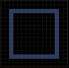
BIG SQUARE
Code
这一题是游戏给出的示例,相对来说难度并不大,整体的思路就是:我们在内存的
@30,@31,@32,@33定义四个常量,分别是1,10,-1,-10。而这个常量则是我们在循环的过程中控制像素点指针移动的变量。
- 1 表示向右移动
- 10 表示向下移动
- -1 表示向左移动
- -10 表示向上移动
1 | MOV 022 @80 000 // set the starting pixel index for the graph we are about to draw |
ADD @80 *C0 @80
ADD @80 *C0 @80 这里我们对 @80 和
*C0 进行求和,并将求和的结果存入
@80,初看这条命令其实会让人有一些疑惑,因为这里用到了
*C0,而 *C0 在前面的指令
MOV 030 @C0 000 中,指向了一个 constant
value 30。
这里,其实我们是在初始化内存的时候,将内存地址的一部分存放了我们需要的操作数,例如:
@30== 001@31== 010@32== -01@33== -10
所以,当我们在调用指令 ADD @80 *C0 @80 时,其实相当于是
num = num + 1; 这条语句。
正如我们在很多地方会提到的,可执行程序会包含所谓的 .data
和 .text,这里的 [@30, @33]
这个区间就可以认为是我们的 .data,而
[@00, @23] 这个区域,则可以认为是我们的 .text,
而 [@80, ..) 这个区间,则是我们的堆栈区间。
一个更直观的图示
在绘制这个简单的BIG
SQUARE的过程中,我们其实把他拆分为了绘制四条边,每条边包含了11个像素点。然后通过
*C0 指向的一个constant
value来控制我们像素点的移动。如果我们修改一下我们的源码,我们可以非常清楚的看到我们像素点的绘制流程:
1 | MOV 022 @80 000 |
这样我们最后得到的图像结果如下:
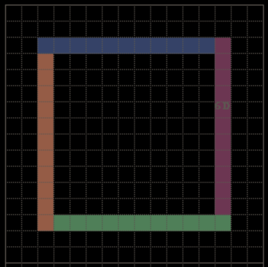
BIG SQUARE II
Code
第二题是画两个正方形,我们的思路是一样的:将一个正方形拆解为四条边,每次画一条边,并通过一个常量值来控制像素点的上下左右移动。区别在于,这次我们需要一个个额外的变量:the total count of pixels per line,这个变量用于控制我们循环输出时每条边包含的像素点数量;具体的代码实现如下:
1 | # .text |
Outputs
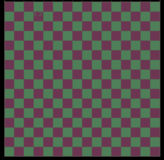
CHECKBOARD
这个问题也不难,思路就是使用FLP指令翻转色彩,但是需要注意的是,我们需要记录移动的次数,因为在换行时我们需要额外翻转一次。
Code
1 | # @80 = first color |
Result
CHECKBOARD II
同样的,这个题我们会使用到
001和00C两个颜色,并且,我们可以注意到:假设横坐标和纵坐标分别为 i 和 j,整个图形可以看做是
0 <= i < 4 && 0 <= j < 4这个图形的递归输出,那么board[i][j]的颜色为:
i % 4 <= 1&&j % 4 <= 1,则颜色是001;i % 4 >= 2&&j % 4 <= 1,则颜色是00C;i % 4 <= 1&&j % 4 >= 2,则颜色是001;i % 4 >= 1&&j % 4 <= 1,则颜色是00C;也就是说,我们可以使用一个
4 * 4的二维数组来计算当前像素点的颜色并着色。此外,如果我们把每个同颜色
2 * 2色块作为一个整体来看,那么每次当我们来到左上的顶点时,我们可以将改区域的全部节点上色,也就是:
- PIX x color
- PIX (x + 1) color
- PIX (x + 10) color
- PIX (x + 11) color
更进一步,在这种情况下,我们可以利用我们在 CHECKBOARD 中使用到的
FLP指令来对颜色进行翻转,可以直接省略掉这个 4 * 4 的二维数组
Code
1 | MOV 001 @80 000 // @80 = current color |
Result
FOUR SQUARES
这题用到了四种不同的颜色:
008,009,00A,00B,所以我们可以预先定义一个变量表示当前颜色,在每次循环结束时递增颜色,整个执行过程可以描述为:
- 初始化参数:
- 初始化 pixel index 为
0;- 初始化 direction index 为
0,控制 pixel index 移动方向;- 初始化 color 到
008;- 画上面的横边,画完后修改索引控制 pixel index 向下移动;
- 画右边的竖边,画完后修改索引控制 pixel index 向左移动;
- 画下面的横边,画完后修改索引控制 pixel index 向上移动;
- 准备画下一个正方形:
- 移动 pixel index 到下一个正方形的起始点;
- Reset direction index;
- color++;
Code
1 | MOV 000 @80 000 // @80 pixel index |
Result
FOUR SQUARES II
这一题,其实还是在画正方形,区别在于,这次画的正方形是一个
N * N的正方形。我们观察到,这四个正方形分别是8 * 8,4 * 4,2 * 2,1 * 1,所以我们可以使用一个变量来存储像素点的数量。
Code
1 | MOV 000 @80 000 // @80 pixel index |
Result
CARPET
到这一题,已经开始略微有一些难度了,我们可以注意到这个图中总共用到了以下四个颜色:
color palette red002purple001green003orange004通过观察,我们可以注意到一个现象,假设使用 row 和 col 表示内存的行和列,那么存在以下逻辑:
对于任意满足 \(\text{row} \in (0, 15]\) 以及 \(\text{col} \in [0, 15)\) 的像素点,他的颜色可以表示为 \(memory[row - 1][col + 1]\)。
使用上面的公式,我们可以生成数组中的前15个像素点,但是最后一列我们也需要单独的记录(其实也可以找到对应的规律,但是没有必要)。
所以我们需要做的就是,使用两个数组分别记录
memory[0][0] ~ memory[0][15]和memory[15][0] ~ memory[15][15],并在程序中递归的去访问并生成图形。更进一步,我们可以发现,如果我们将
memory[0][0] ~ memory[0][15]和memory[1][15] ~ memory[15][15]这里总共31个元素,变换成一个长度为31的一维数组,假设这个数组为transfomer。我们会发现:
- \(memory[0][0]\) ~ $ memory[0][15]$ 对应的是 \(transfomer[0]\) ~ \(transformer[15]\);
- \(memory[1][0]\) ~ $ memory[1][15]$ 对应的是 \(transfomer[1]\) ~ \(transformer[16]\);
- ...
- \(memory[i][0]\) ~ $ memory[i][15]$ 对应的是 \(transfomer[i]\) ~ \(transformer[i + 15]\);
Code
1 | // @01 point to the first parameter of PIX |
Result
CARPET-II
这题非常简单,在这一题中,我们用到了以下两个颜色:
color palette Dark Green003Light Green00B整个绘制过程也不复杂,可以细分为两个步骤:
- 绘制一个色块为颜色一,绘制后续三个色块为颜色二,绘制随后的一个色块为颜色一;
- 翻转颜色一和颜色二,跳转到
<1>,循环直到将所有颜色绘制完毕。
Code
1 | PIX @2E @2F 000 |
Result
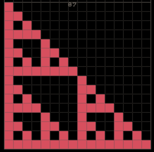
SIERPINSKI
这题相对之前的题难度提升了非常多
这一题我们要绘制的是:SIERPINSKI TRIANGLE(谢尔宾斯基三角形),根据描述,可以如下生成:
It can be created by starting with one large, equilateral triangle, and then repeatedly cutting smaller triangles out of its center.
Code for drawing a triangle
在我们开始绘制谢尔宾斯基三角形之前,我们可以先试试如何绘制一个简单的三角形,这个其实很简单,我们先找到一个起点,在后面的每次循环中:
- 我们将起点向下移动一格作为竖边,并作为下次绘制竖边的起点;
- 我们将起点向下移动一格后向右移动一格(也有可能是向左移动)作为斜边,并作为下次绘制斜边的起点;
为了实现更简便,我们可以在最开始时就定义两个点,这两个点重合作为起始点,随后分别作为竖边和斜边进行移动。
这样,我们就得到了我们需要的竖边和斜边,随后我们将竖边的点开始向斜边的点开始移动,直到竖边的点和斜边的点重合。
1 | PIX @28 008 000 |
Result for drawing a triangle
Code for Sierpinski triangle
参考在 SIERPINSKI TRIANGLE 中的详细描述
Code for Sierpinski triangle(mini version)
根据我们之前的算法,我们还可以实现一个不使用多线程,而是通过最短的代码量来实现的结果
Result
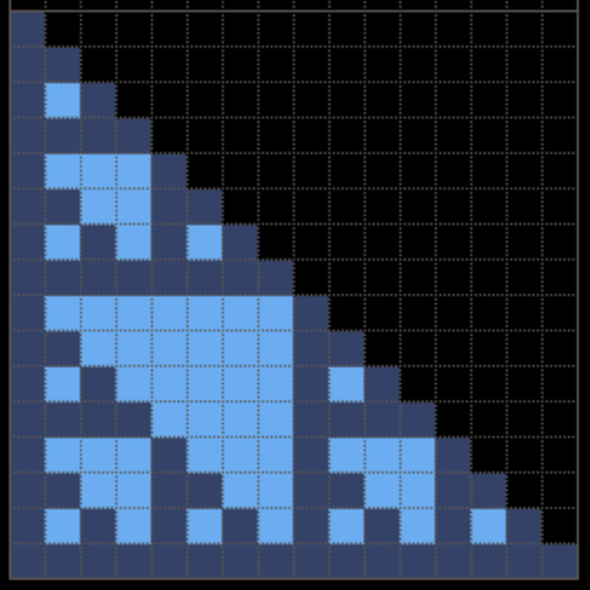
SIERPINSKI II
Code
这一题,和刚才的题非常相似,区别在于:
- 使用的颜色变化了;
- 现在三角形内部的空余部分也需要进行上色了;
现在三角形的边使用的颜色是 001,而内部填充的则是
00C;
1 | PIX 000 @27 000 |
Result
SMILEY FACE
Code
这一题,我总共想到了以下几种思路:
- 通过编码压缩来表示图片中的上色区域和飞上色区域:
- 通过二元组
[start, end]来表示一个连续的上色区域,例如[06, 09]表示第一行的上色区域,而且这样对于跨行的连续上色区域可以使用一个数组来表示:例如:[6A, A2]这一大片区域只需要一个二元组即可表示,对于这种表示方式,我们总共需要25个二元组来表示。- 通过二元组
[start, end]来表示连续的非上色区域,例如[00, 05]表示第一行开头的非上色区域,[0A, 13]分别表示跨第一行和第二行的非上色区域,对于这种表示方式,我们总共需要20个二元组来表示。没有想到有什么好的方法来优化这个逻辑,可以尝试使用位图或者其他的方式。
1 | MOV *1C @1A 000 |
Result

MARIO
这个思路和上面的思路其实是一样的,就直接贴代码了
1 | MOV @1A @06 001 |
Result

引用
问题
这里总结了一下,在解题过程中碰见,但是尚未解决的问题,可能是因为个人能力有限,也有可能是需要投入的时间精力过多。
线程创建算法
这个公式暂时还没有推理证明过程。
线程创建算法需要满足一个公式:假设存在一个大于2的正整数
N,该正整数 N 的二进制 place value
可以表示为:\(b_mb_m-1...b_i...b_1b_0\)
,如果从高到低遍历N的place value,并且按照如下规则计算:
- 存在 \(x\) 初始值为 1;
- 如果 \(b_i\) 为 1,则
x = 2 * x; - 如果 \(b_i\) 为 0,则
x = (2 * x) - 1;
递归计算完成后,\(x\) 的值等于 \(N+1\)
Siérpinski Triangle 的点绘制算法
在Siérpinski Triangle的绘制过程中,有用户给出了一个非常非常巧妙的方法,参考 BOX-256 Threads - A practical example 中提出的:
1 | 00 - THR 004 ; |
这段代码的其他部分解读可以参考本文的 SIERPINSKI TRIANGLE,但是这里还存在的一个问题是,下面的代码的工作原理只是根据代码以及图形倒推,并没有给出严禁的证明。
1 | 20 - ADD @29 @28 @38 ; 4th thread |
其他
暂时来说,我们目前大部分方法都是使用的比较简单原始的暴力破解,其实我们还可以使用很多手段来优化,不过这是一个处于学习目的的小练手项目,就不准备再继续投入更多的时间了。